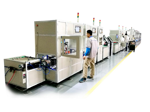
Working Principle and Composition Structure of Bearing Wear Testing Machines
Bearing wear leads to increased internal clearance, which is a major cause of bearing failure over prolonged use. This results in poor mechanical operation and, in severe cases, complete equipment shutdown. The development of bearing wear testing machine technology is a prerequisite for addressing bearing wear issues. Today, the editorial team will take you through the working principle and composition structure of bearing wear testing machines.
I. Working Principle of Bearing Wear Testing Machines
- Electrical Signal to Oil Flow Conversion
High-pressure oil from the oil source is filtered and enters the electro-hydraulic servo valve. Meanwhile, the electrical signal from the electronic control system is compared with feedback signals from strain gauges, displacement sensors, or load cells. This signal difference is amplified and sent to the electro-hydraulic servo valve, which converts the electrical signal into oil flow. The high-pressure oil is then delivered to the upper and lower chambers of the actuator, driving the piston to move. The load cell is connected to the piston rod and indenter to monitor real-time load.
- Closed-Loop System Control
The load and displacement applied to the test piece (bearing) in the cylinder are measured by load cells and displacement sensors, ensuring the test piece’s response matches the set load signal from the electronic control system and load sensors. The torsion unit transmits torque via a servo motor and reducer; torsion angle is measured by an angular displacement sensor, and torque is measured by a torque sensor. Together, these components form a closed-loop control system for precise torque regulation.
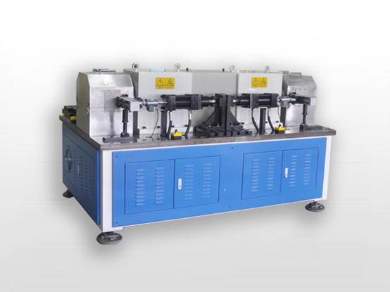
II. Composition Structure of Bearing Wear Testing Machines
- Main Component Systems
The testing machine consists of three core systems: the main machine system, hydraulic system, and electronic control system.
- Main Machine: Comprises two parts—radial loading and torsion (both equipped with torsion angle measurement). The radial loading section features a closed frame (composed of columns, crossbeams, and a workbench), along with a servo cylinder, test fixtures, load cells, indenters, and wear measurement devices.
- Configuration of Different Models
- The 300 kN and 100 kN models share a similar basic structure and are capable of conducting wear tests on spherical plain bearings under high and low temperature conditions, as they are equipped with environmental chambers with a temperature range of -70℃ to 350℃.
- The 700 kN model, while structurally consistent, is additionally fitted with temperature measurement and cooling devices. Due to the high radial loads and significant friction generated during torsion, this model produces substantial heat during testing, requiring cooling to maintain the test bearing temperature below 80℃.
The above covers the working principle and composition structure of bearing wear testing machines. These machines continuously measure and record wear levels, providing valuable data for research and analysis. Kaiyuan Intelligence has extensive experience in the R&D and production of bearing testing machines. For inquiries or procurement needs related to our products, please feel free to contact us via phone.
What Is a Heavy-Duty Truck Wheel Hub Bearing Testing Machine? What Are Its Functions?
Functions and Equipment Types of Bearing Testing Machines
Related Article